- Do you need help? Here Us:
- +86 13169905499
- sunny@handaspring.com
- Wechat:13169905499
 English
  中文 (中国)
 Chenzhou, Hunan, China(423000)
- 2026年4月14日
- handasprings
- Read: 260
Discover how U spring-energized seals deliver reliable performance in semiconductor and aerospace applications. Learn about U spring design, material options, custom sizing, and how they outperform standard seals in demanding environments.
Introduction: The Growing Demand for High-Performance Seals
In the semiconductor and aerospace industries, equipment reliability is non‑negotiable. A single seal failure in a wafer fabrication chamber can ruin millions of dollars worth of product. A leak in an aircraft hydraulic actuator can compromise flight safety. These extreme environments demand sealing solutions that go far beyond standard O‑rings.
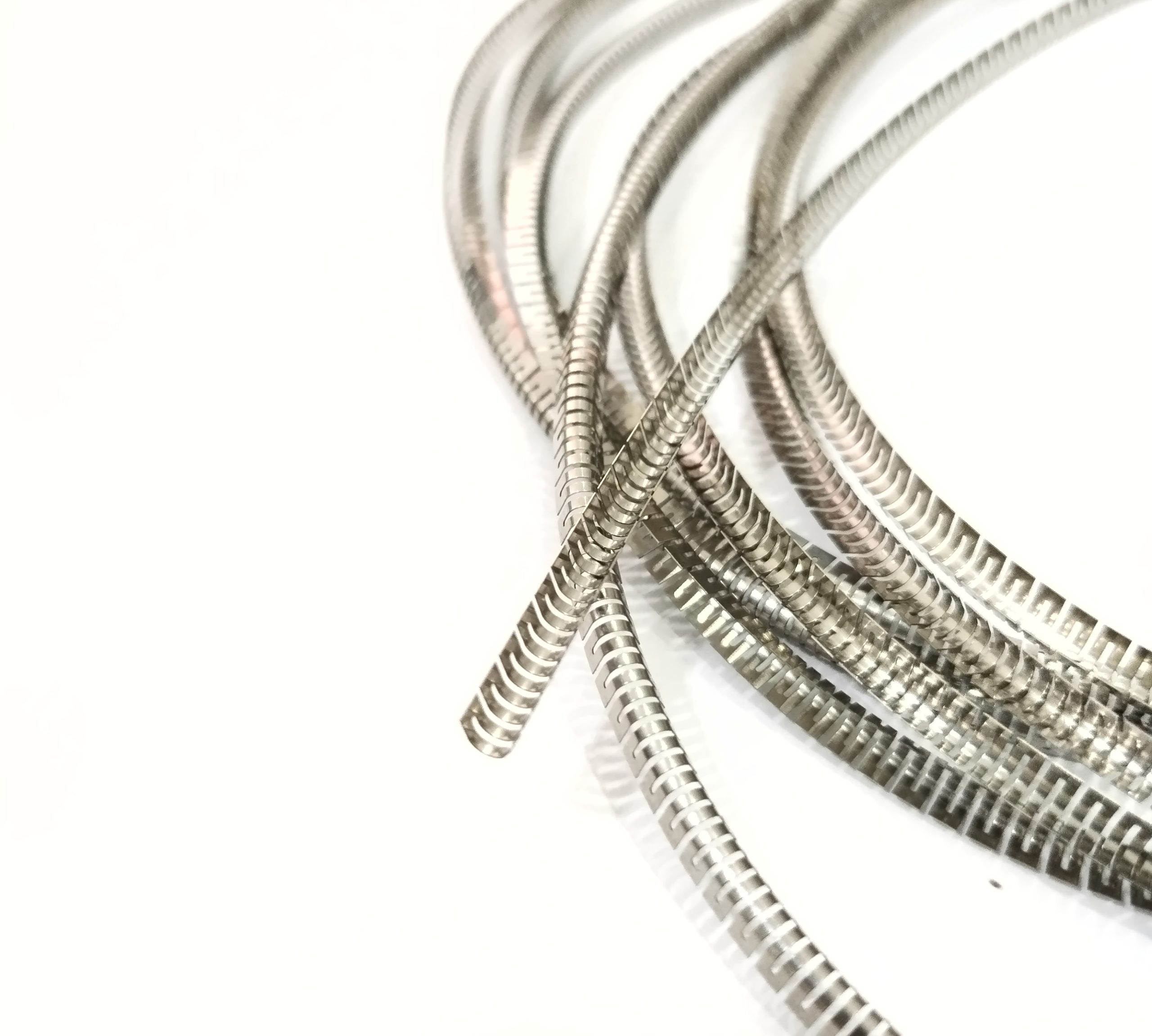
Spring-energized seals have emerged as the gold standard for demanding static and dynamic applications. At the heart of these seals lies a precision‑engineered metal spring – and the U spring (also known as cantilever U spring or meander spring) is one of the most popular and versatile energizers available.
This article explores why U spring‑energized seals are trusted in semiconductor and aerospace applications, how they are designed, what materials are available, and how to select the right configuration for your critical equipment.
What Is a U Spring‑Energized Seal?
A spring‑energized seal consists of two main components: a polymer seal jacket (typically PTFE, UHMW‑PE, PEEK, or other advanced thermoplastics) and a metal spring that provides the sealing force. The U spring is a cantilever‑type spring formed from a thin metal strip into a repeating U‑shaped pattern. When installed inside the seal jacket, the spring pushes the sealing lip against the mating surface, creating a tight, leak‑proof barrier even under extreme conditions.
Unlike standard O‑rings that rely solely on the rubber’s elasticity, spring‑energized seals maintain consistent contact pressure over a wide range of temperatures, pressures, and wear conditions.
Key Components of a U Spring‑Energized Seal
| Component | Function | Typical Materials |
|---|---|---|
| Seal Jacket | Provides chemical resistance, low friction, and wear protection | PTFE, UHMW‑PE, PEEK, PVDF |
| U Spring | Supplies constant energizing force to the sealing lip | Stainless steel, Elgiloy, Inconel, Hastelloy |
Why U Spring for Semiconductor Equipment?
Semiconductor manufacturing involves some of the most demanding sealing conditions in industry: ultra‑high vacuum (UHV), aggressive process gases (e.g., Cl₂, BCl₃, NF₃), high temperatures (150‑250°C), and extreme cleanliness requirements. Standard elastomeric seals quickly degrade under these conditions. Spring‑energized seals with U springs have become the standard solution for critical semiconductor applications.
1. Ultra‑High Vacuum Compatibility
Semiconductor processes such as physical vapor deposition (PVD), chemical vapor deposition (CVD), and etching require vacuum levels down to 10⁻⁹ Torr. U spring‑energized seals provide:
-
Low outgassing – PTFE jackets meet UHV requirements
-
Consistent sealing force – even as the pump pulls vacuum
-
Helium leak rates < 1×10⁻⁹ cc/sec
2. Aggressive Chemical Resistance
Many semiconductor processes use reactive gases that attack conventional elastomers. PTFE jacket with U spring energizer resists:
-
Halogen gases (fluorine, chlorine, bromine)
-
Acidic etchants (HF, HCl, H₂SO₄)
-
Organic solvents used in cleaning cycles
3. Wide Temperature Range
U spring‑energized seals operate from ‑200°C to +260°C (with appropriate jacket and spring materials), covering everything from cryogenic cooling loops to high‑temperature bake‑out cycles.
4. Particle Generation Control
Semiconductor cleanrooms (ISO Class 3‑5) require seals that generate minimal particles. U springs are designed with smooth edges and polished surfaces to prevent shedding. The PTFE jacket provides low friction and low wear, minimizing contamination.
Why U Spring for Aerospace Applications?
Aerospace seals face a different set of challenges: extreme temperature swings (‑50°C to +200°C), high pressures (up to 5,000 psi or more), exposure to jet fuel, hydraulic fluids (Skydrol, MIL‑PRF‑83282), and de‑icing chemicals. Vibration, rapid pressure cycling, and long maintenance intervals add further demands.
1. Hydraulic System Seals
Aircraft hydraulic systems operate at pressures up to 5,000 psi. U spring‑energized seals provide:
-
Zero leakage over thousands of flight cycles
-
Wear compensation – as the PTFE lip wears, the spring maintains contact
-
Low friction – reduces heat generation and energy loss
2. Fuel System Seals
Jet fuel (Jet A, JP‑8, JP‑10) aggressively swells standard elastomers. PTFE with U spring energizer is dimensionally stable and chemically inert, ensuring reliable sealing for fuel pumps, valves, and line connections.
3. Landing Gear and Actuators
Landing gear seals must withstand high shock loads, dirt, and extreme weather. U spring‑energized seals with robust PTFE compounds provide long service life, reducing maintenance intervals.
4. Weight and Space Savings
U springs have a low profile and can be designed into compact grooves, saving valuable weight and space – critical factors in aerospace design.
Design Advantages of U Spring‑Energized Seals
Distributed Load Profile
Unlike V springs that create a concentrated point‑load, U springs provide a more even, distributed force along the sealing lip. This is beneficial for:
-
Low friction – the load is spread, reducing local wear
-
Uniform sealing – avoids high‑pressure lines that could damage soft mating surfaces
-
Static and slow dynamic applications – where even pressure is preferred over aggressive scraping
Linear Load‑Deflection Curve
U springs exhibit a linear load‑deflection characteristic (force increases proportionally with compression). This predictable behavior allows engineers to calculate exact sealing force based on gland dimensions.
Moderate Deflection Range
U springs have a moderate deflection range – typically 0.5‑1.5 mm depending on spring size. This is sufficient for most well‑controlled aerospace and semiconductor applications where gland tolerances are tight.
Stackability
Multiple U springs can be stacked inside a single seal jacket to increase sealing force without changing the spring geometry. This is useful for high‑pressure applications (up to 30,000 psi).
Material Options for U Springs
The U spring itself must be made from materials that maintain elasticity under extreme conditions. Common materials include:
| Material | Temperature Range | Key Properties | Typical Aerospace/Semi Applications |
|---|---|---|---|
| 301 Stainless Steel | -40°C to 250°C | High strength, cost‑effective | General industrial, low‑corrosion environments |
| 302 Stainless Steel | -40°C to 250°C | Similar to 301, good formability | Standard spring applications |
| 304 Stainless Steel | -200°C to 250°C | Excellent corrosion resistance | Cleanroom, food, pharmaceutical |
| 316 Stainless Steel | -200°C to 250°C | Superior corrosion resistance, especially to chlorides | Marine, offshore, chemical |
| 17-7PH | -200°C to 315°C | Precipitation‑hardening, high strength | Aerospace, high‑stress applications |
| Inconel X‑750 | -200°C to 540°C | Excellent high‑temperature strength, oxidation resistance | Jet engines, high‑temperature valves |
| Elgiloy | -250°C to 400°C | High strength, non‑magnetic, excellent fatigue life | Medical implants, aerospace actuators |
| Hastelloy C‑276 | -200°C to 400°C | Outstanding resistance to pitting and stress corrosion | Chemical processing, sour gas |
Plating Options
For added corrosion resistance or galvanic compatibility, U springs can be plated with:
-
Tin – good conductivity, low cost
-
Nickel – hard, wear‑resistant, good barrier
-
Silver – highest conductivity, anti‑oxidant
-
Gold – excellent corrosion resistance, biocompatible
Seal Jacket Materials for Semiconductor & Aerospace
The U spring is only half the story. The polymer jacket must be selected to match the operating environment.
| Jacket Material | Temperature Range | Chemical Resistance | Friction | Typical Applications |
|---|---|---|---|---|
| Virgin PTFE | -200°C to 260°C | Excellent | Lowest | General semi/aero |
| 25% Glass‑filled PTFE | -200°C to 260°C | Good (reduced) | Low | Higher wear resistance |
| Carbon‑filled PTFE | -200°C to 260°C | Good | Low | Conductive, anti‑static |
| UHMW‑PE | -200°C to 80°C | Good | Very low | Low‑temp dynamic |
| PEEK | -60°C to 250°C | Excellent | Moderate | High load, high temp |
| PI (Vespel) | -200°C to 300°C | Excellent | Moderate | Extreme temp, high load |
Performance Comparison: U Spring vs. Other Energizers
| Parameter | U Spring | V Spring | Canted Coil Spring |
|---|---|---|---|
| Load curve | Linear | Linear | Near‑constant |
| Deflection range | Moderate | Wide | Wide |
| Contact pattern | Distributed | Point‑load | Multiple points |
| Best for | Static, slow dynamic, clean media | Viscous media, wide tolerance | High speed, rotary, EMI shielding |
| High‑temp resistance | Good (to 260°C) | Excellent (to 400°C) | Good (to 260°C) |
| Cost | Low‑moderate | Moderate | Higher |
For semiconductor and aerospace applications where tolerances are well‑controlled and media are clean, the U spring offers an excellent balance of performance and cost.
Customization Capabilities
Standard Sizes
U springs are available in standard cross‑sections (typically from 0.5 mm to 6 mm spring height) and can be supplied as:
-
Continuous length (spool) – customer cuts to required length
-
Pre‑cut and welded rings – ready‑to‑install
Custom Dimensions
For non‑standard gland geometries, we can manufacture U springs with:
-
Custom cross‑section height and width
-
Custom wire thickness (affects spring force)
-
Custom coil density (more coils = higher force)
-
Custom diameters from 3 mm to over 2,000 mm
Force Tuning
The spring force can be precisely adjusted by changing:
-
Wire thickness – thicker wire = higher force
-
Spring height – taller spring = lower spring rate
-
Number of U‑shaped segments – more segments = more uniform force
Quality Assurance and Testing
U springs for semiconductor and aerospace applications require rigorous quality control.
Dimensional Inspection
-
Outer diameter, inner diameter, cross‑section height/width measured to ±0.05 mm
-
End gap control for welded rings
Material Certification
-
Mill test reports (MTC) traceable to heat/lot number
-
RoHS compliance certification
-
NACE MR0175 for sour gas (if applicable)
Performance Testing
-
Load‑deflection testing – verify spring rate at specified compression
-
Compression set testing – ensure long‑term force retention
-
Fatigue testing – thousands of cycles to validate life
Documentation
Each shipment includes:
-
Certificate of conformance
-
Dimensional inspection report
-
Material certificate
-
Lot traceability
Installation Guidelines for U Spring‑Energized Seals
Proper installation is critical for optimal performance.
Gland Design Recommendations
| Parameter | Recommended Value |
|---|---|
| Gland depth | Spring height × 0.8 to 0.9 (for 10‑20% compression) |
| Gland width | Spring width + 0.1‑0.2 mm |
| Corner radius | ≥0.2 mm |
| Surface finish | Ra ≤0.8 μm (mating surface) |
Installation Steps
-
Inspect the gland for burrs, chips, or damage.
-
Lubricate the seal jacket with compatible grease (e.g., Krytox for oxygen service, silicone for general use).
-
Insert the U spring into the seal jacket cavity – ensure it lies flat without twisting.
-
Install the assembled seal into the gland using tapered tools to avoid cutting the jacket.
-
Verify that the seal is seated evenly before final assembly.
Common Mistakes to Avoid
-
Over‑compression – reduces spring life, may cause extrusion
-
Under‑compression – insufficient sealing force, leads to leaks
-
Twisted spring – uneven load distribution
-
Damaged jacket – cuts or nicks compromise sealing
Case Study: Semiconductor Etch Chamber Door Seal
Challenge: A semiconductor manufacturer experienced frequent seal failures on an etch chamber door. The original elastomeric O‑rings degraded rapidly due to halogen gas exposure, causing unplanned downtime and yield loss.
Solution: A spring‑energized seal with U spring energizer and PTFE jacket was designed. The PTFE provided chemical resistance to Cl₂ and BCl₃, while the 316 stainless steel U spring maintained consistent force despite temperature cycling (50°C to 150°C).
Results:
-
Seal life extended from 2 weeks to over 12 months
-
No detectable leakage (helium mass spectrometer)
-
Reduced maintenance costs by 80%
Case Study: Aircraft Hydraulic Actuator Seal
Challenge: An aerospace OEM needed a seal for a flight control actuator operating at 5,000 psi with Skydrol hydraulic fluid. The seal had to withstand ‑50°C to 135°C and provide zero leakage for 10,000 flight cycles.
Solution: A custom U spring‑energized seal with PTFE jacket and 17-7PH stainless steel U spring was developed. The U spring’s linear load curve provided predictable sealing force, and the PTFE resisted Skydrol attack.
Results:
-
Zero leakage after 15,000 cycles
-
Passed all qualification tests (vibration, thermal shock, pressure cycling)
-
Approved for production
How to Order Custom U Spring‑Energized Seals
When requesting a quotation, please provide the following information:
-
Gland dimensions (or hardware drawing)
-
Operating conditions – temperature, pressure, media, motion type
-
Performance requirements – leak rate, cycle life, certification needs
-
Jacket material preference (if known)
-
Spring material preference (if known)
-
Quantity – prototype or production
Our engineering team will then recommend the optimal U spring configuration and provide a quotation with lead time.
Conclusion: U Spring – The Reliable Choice for Critical Applications
U spring‑energized seals combine the chemical resistance and low friction of advanced polymers with the predictable, distributed force of a precision‑engineered metal spring. For semiconductor and aerospace applications where reliability, cleanliness, and performance are paramount, the U spring offers:
-
Proven performance in vacuum, aggressive chemicals, and wide temperatures
-
Customizable force to match exact gland designs
-
Cost‑effective compared to other energizer types
-
Long service life – reduces downtime and maintenance costs
Whether you need seals for wafer fabrication chambers, aircraft hydraulic systems, or space‑grade valves, U spring‑energized seals deliver the high performance your application demands.
Ready to upgrade your sealing solution? Contact our engineering team with your application parameters for a custom U spring recommendation and quotation.