English
  中文 (中国)
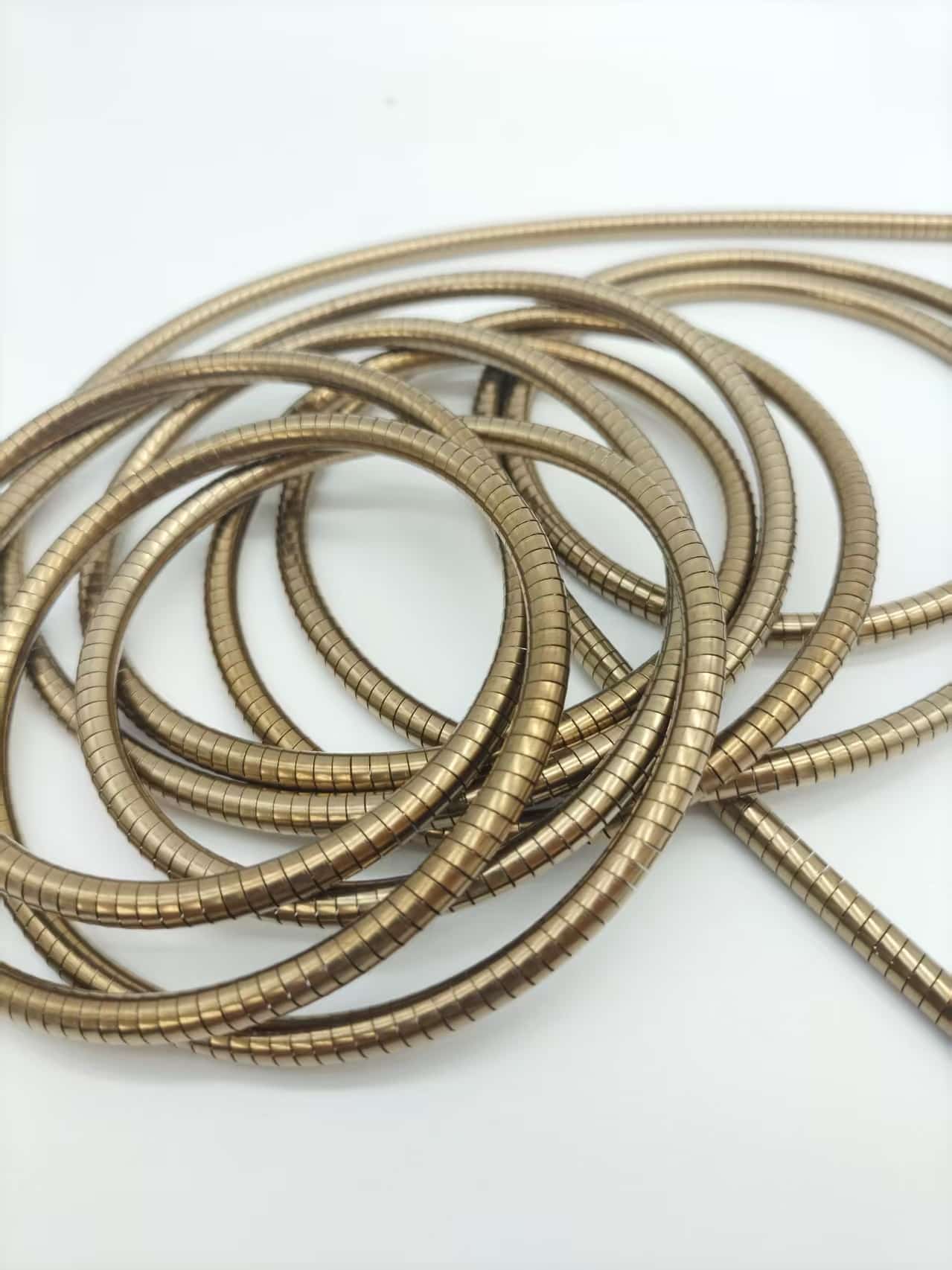

Introduction
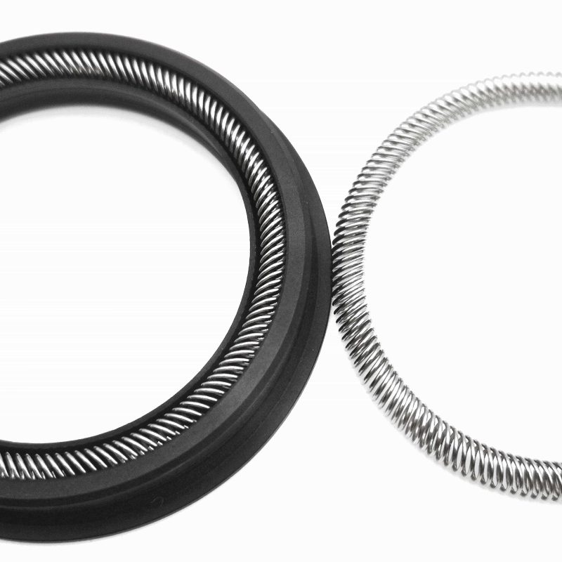
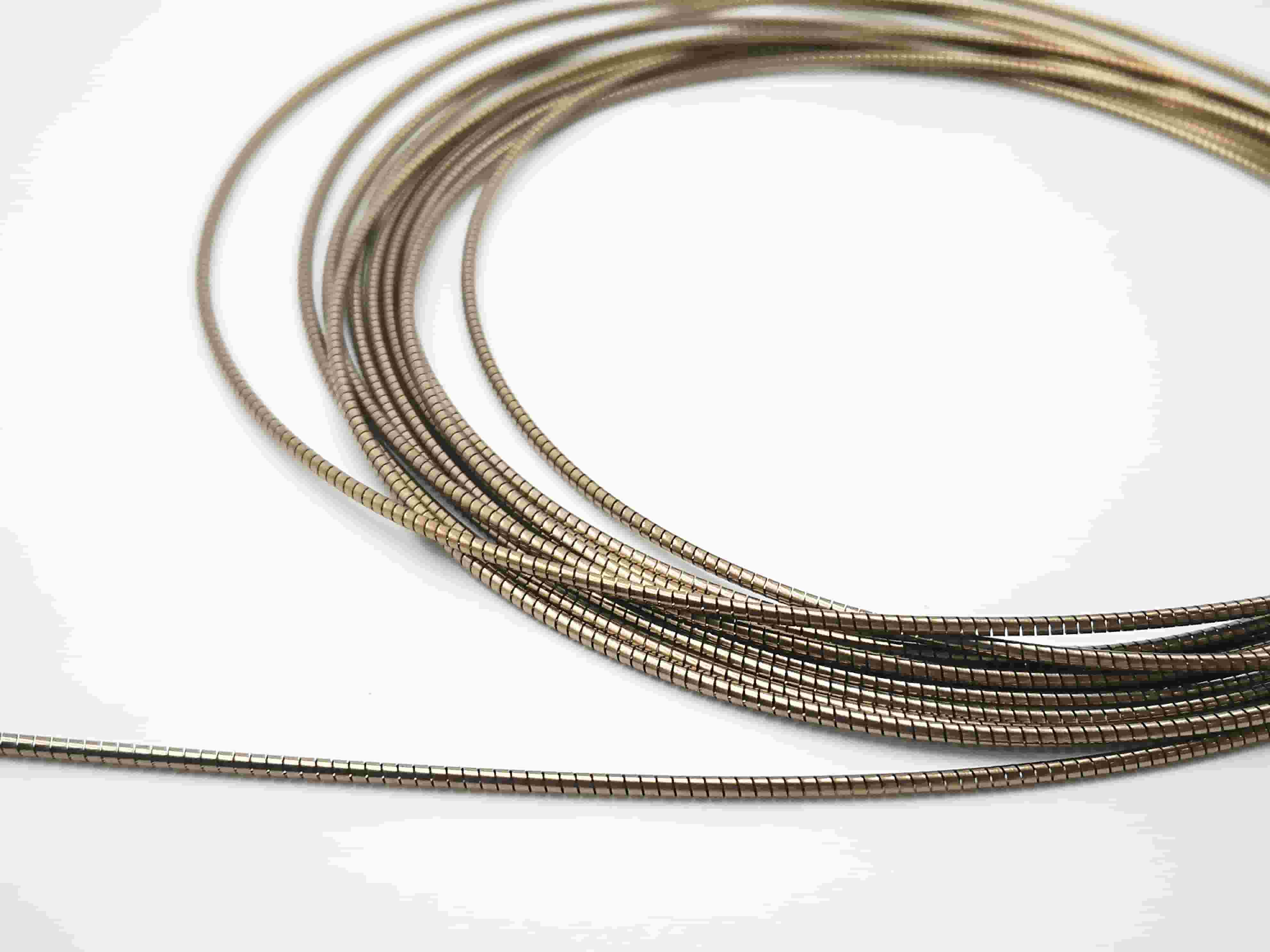
When designing a Spring Energized Seal, engineers often focus on sealing materials, operating pressure, and groove dimensions. However, one critical component is frequently overlooked—the Helical Spring.Although it is hidden inside the seal, the Helical Spring is responsible for maintaining continuous contact pressure throughout the seal’s service life. Choosing the wrong spring material can significantly reduce sealing performance, increase friction, accelerate wear, and shorten equipment life.
For engineers working in industries such as semiconductor manufacturing, oil & gas, aerospace, medical devices, and industrial hydraulics, selecting the right Helical Spring material is not simply a matter of choosing stainless steel or a high-strength alloy. It requires balancing operating temperature, media compatibility, corrosion resistance, fatigue life, and overall system reliability.This guide compares the most commonly used Helical Spring materials under typical engineering conditions and explains how to select the most suitable material for your specific application.
Why Does Helical Spring Material Matter?
The primary function of a coil spring is to provide preload and to continuously compensate for seal wear, thermal expansion, pressure fluctuations, and manufacturing tolerances throughout the equipment’s entire life cycle.If the spring material is not properly matched to the application, several problems may occur:
•Excessively Rapid Loss of Elasticity: After a period of use, the spring’s thrust decreases significantly, making it unable to continuously provide a stable preload to the seal.
•Increased Permanent Deformation: After prolonged compression, the spring cannot return to its original shape, resulting in reduced resilience and compromised sealing performance.
•Seal leakage: Due to insufficient spring thrust, the sealing surfaces cannot maintain a tight seal at all times, allowing the medium to leak through the gaps.
•Corrosion failure: In humid, chemical, or salt spray environments, springs are prone to rust or corrosion; in severe cases, they may even fracture and fail.
•Reduced service life: Springs are more susceptible to fatigue, wear, or loss of elasticity, requiring early replacement and increasing equipment maintenance costs.
For this reason, selecting the correct Helical Spring material is often just as important as selecting the sealing material itself.To learn more about Helical Spring products and Spring Energized Seals, visit:Introduction to Pansefeng Springs
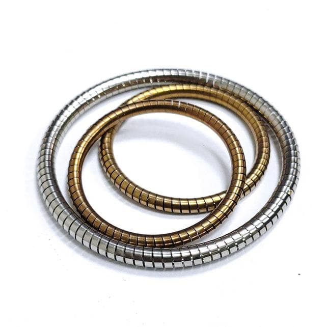
The Four Most Common Helical Spring Materials
Several materials are commonly used for Helical Spring manufacturing in Spring Energized Seal applications. Each offers different advantages depending on the operating environment.
| Material |
Primary Advantages |
Typical Applications |
| 302/304 Stainless Steel | Cost-effective, versatile | General industrial equipment |
| 316 Stainless Steel | Excellent corrosion resistance | Chemical processing, food equipment, marine applications |
| Elgiloy® | Outstanding fatigue life and corrosion resistance | Semiconductor, aerospace, high-end industrial equipment |
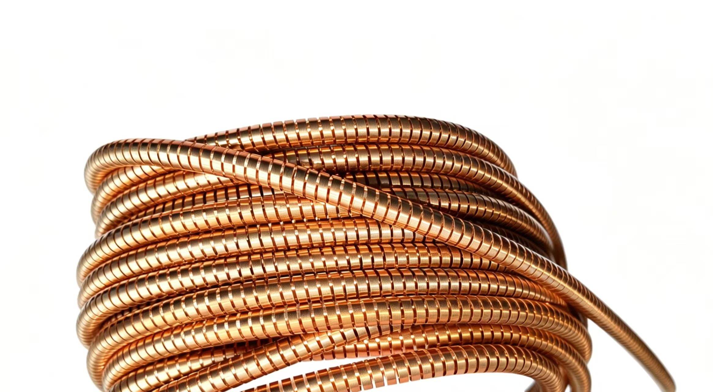
| Beryllium Copper (C17200) | High elasticity and electrical conductivity | EMI shielding, electrical contacts, specialty sealing applications |
Among these materials, 316 Stainless Steel remains one of the most widely used choices because it offers an excellent balance between performance, corrosion resistance, and cost.For applications requiring exceptional fatigue resistance and long service life, Elgiloy® is often the preferred material.Meanwhile, Beryllium Copper (C17200) is typically selected when electrical conductivity and stable spring performance are both required.
Performance Comparison of Common Helical Spring Materials
To better understand the performance differences between these materials, the following table summarizes a typical engineering evaluation performed under representative Spring Energized Seal operating conditions.
Test Conditions
| Test Item | Condition |
| Operating Temperature | 150°C |
| System Pressure | 20 MPa |
| Spring Compression | 25% |
| Working Medium | Hydraulic Oil (ISO VG 46) |
| Test Cycles | 1,000,000 Cycles |
| Test Frequency | 1 Hz |
Performance Results
| Material | Fatigue Resistance | Corrosion Resistance | High Temperature | Relative Cost |
| 302 SS | Good | Fair | Good | Low |
| 316 SS | Very Good | Excellent | Very Good | Medium |
| Elgiloy | Excellent | Outstanding | Excellent | High |
| C17200 | Very Good | Very Good | Good | High |
The comparison highlights several important engineering observations:
- •Elgiloy® provides the highest long-term spring force retention, making it well suited for applications requiring extended service life.
- •316 Stainless Steel offers the best overall balance between performance, corrosion resistance, and cost, making it a preferred choice for many industrial sealing systems.
- •Beryllium Copper (C17200) combines excellent elasticity with electrical conductivity, making it ideal for specialized applications where both mechanical and electrical performance are required.
- •302 Stainless Steel remains a practical solution for general-purpose applications where cost is a primary consideration.
Engineering Note: The values shown above represent typical reference data generated under controlled laboratory conditions. Actual performance may vary depending on spring geometry, wire diameter, heat treatment, compression ratio, operating media, and application-specific design requirements.
If you are selecting a Helical Spring for a new sealing project and are unsure which material best matches your operating conditions, our engineering team can help evaluate your application and recommend the most suitable solution.Contact our engineers:Contact Our Engineering Team。
How to Select the Right Helical Spring Material for High-Temperature Applications
For many sealing systems, the service life of a Helical Spring is influenced not only by the maximum operating temperature but also by its ability to maintain consistent spring force during long-term exposure to elevated temperatures.A spring may continue to operate mechanically at high temperatures, but if stress relaxation occurs over time, the preload applied to the seal will gradually decrease. As a result, sealing performance may deteriorate, increasing the risk of leakage and reducing overall system reliability.
When selecting a Helical Spring for high-temperature applications, engineers should evaluate more than just the maximum temperature rating. The following material properties are equally important:
•Long-Term Temperature Resistance: Whether performance remains stable during long-term operation at high temperatures.
•Stress Relaxation Resistance: Whether the material can maintain stable elasticity and preload after prolonged compression.
•Oxidation Resistance: Whether the material is prone to oxidation or corrosion in high-temperature environments, which could affect its service life.
•High-Temperature Fatigue Life: Whether the material can operate for an extended period without failure when subjected to repeated compression at high temperatures.
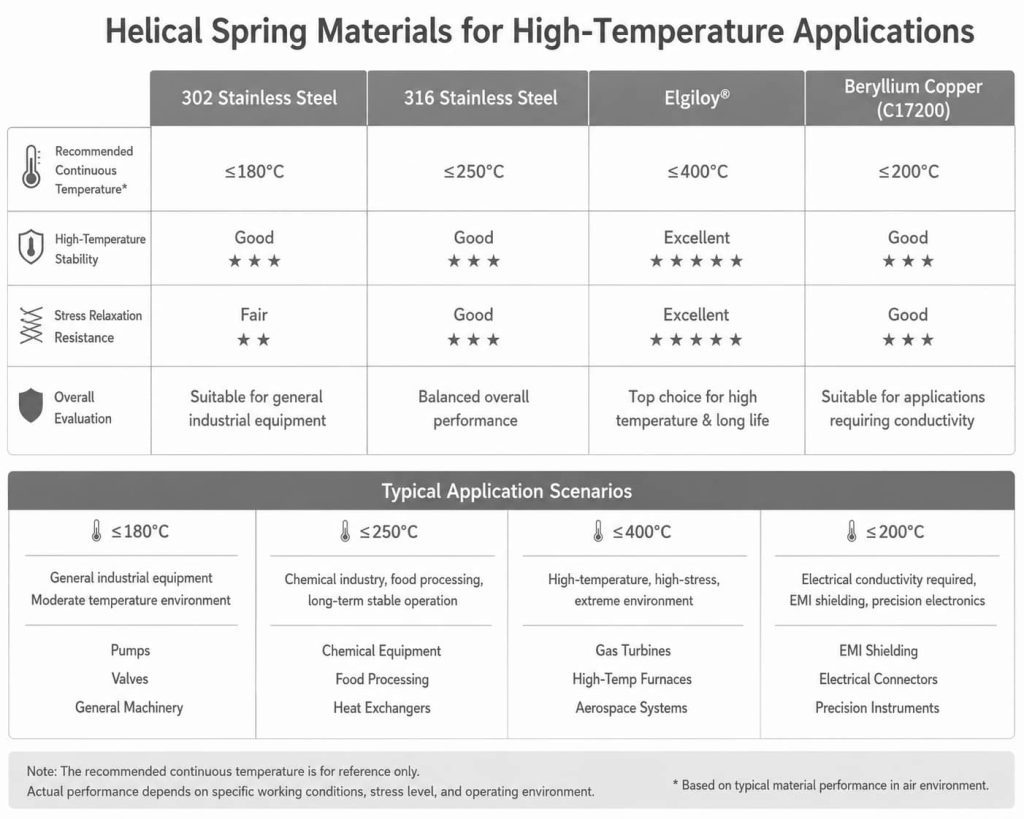
Typical High-Temperature Performance of Common Helical Spring Materials
The table below summarizes the typical characteristics of commonly used Helical Spring materials in elevated-temperature environments.
| Material | Recommended Continuous Operating Temperature | High-Temperature Stability | Stress Relaxation Resistance | Engineering Assessment |
| 302 Stainless Steel | Up to 180°C |
Good |
Fair | Suitable for general industrial applications |
| 316 Stainless Steel | Up to 250°C | Very Good |
Good |
Excellent balance between performance and cost |
| Elgiloy | Up to 400°C | Excellent | Excellent | Preferred for demanding high-temperature sealing applications |
| Beryllium Copper (C17200) | Up to 200°C |
Good |
Good |
Ideal where both elasticity and electrical conductivity are required |
Note: The recommended operating temperatures shown above are general engineering references. Actual performance depends on spring geometry, compression ratio, operating media, duty cycle, and overall system design.
For long-term, high-temperature sealing applications, Elgiloy® Helical Springs are often selected because of their outstanding resistance to stress relaxation and excellent fatigue performance.For most industrial equipment, however, 316 Stainless Steel Helical Springs remain one of the most popular choices due to their balanced combination of corrosion resistance, mechanical performance, and cost-effectiveness.
If your sealing system operates under elevated temperatures and requires long-term reliability, our engineering team can help recommend the most appropriate Helical Spring material based on your specific application.Contact our engineering team:Free Plan Development。
How to Select a Helical Spring Material for Corrosive Environments
In industries such as oil & gas, chemical processing, marine engineering, and food processing, a Helical Spring must withstand not only repeated mechanical loading but also continuous exposure to corrosive environments.
If the spring material does not provide sufficient corrosion resistance, the following issues may occur over time:
•Pitting Corrosion: Corrosion pits form on the surface, which can easily lead to fracture.
•Crevice Corrosion: Corrosion occurs within the gaps between coils, reducing structural strength.
•Surface Oxidation: Rust or an oxide layer forms, increasing friction and wear.
•Reduction in Spring Cross-Sectional Area: Continuous loss of metal reduces load-bearing capacity.
•Decreased Elasticity: Preload weakens, reducing sealing performance and increasing the risk of leakage.
These factors can significantly reduce sealing reliability and shorten the service life of the entire sealing system.For this reason, corrosion resistance should be considered alongside mechanical performance during material selection.
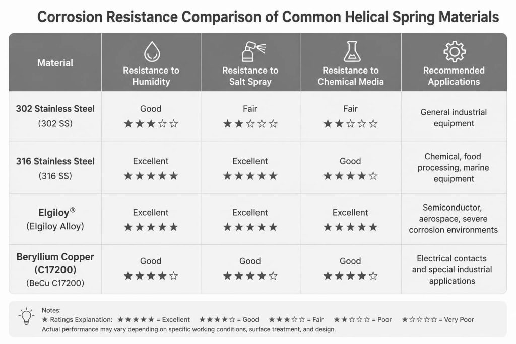
Corrosion Resistance Comparison of Common Helical Spring Materials
| Material |
Humid Environment |
Salt Spray Resistance | Chemical Resistance | Typical Applications |
| 302 Stainless Steel | Good | Fair | Fair | General industrial equipment |
| 316 Stainless Steel | Excellent | Excellent | Good | Chemical processing, food equipment, marine applications |
| Elgiloy | Excellent | Excellent | Excellent | Semiconductor, aerospace, highly corrosive environments |
| Beryllium Copper (C17200) | Good | Good | Good | Electrical contacts and specialty industrial applications |
For equipment operating continuously in humid, saline, or chemically aggressive environments, 316 Stainless Steel and Elgiloy® generally provide superior long-term reliability.
Recommended Helical Spring Materials by Industry
Different industries place different demands on sealing systems. As a result, the most suitable Helical Spring material also varies depending on the application.
| Industry |
Recommended Material |
Primary Design Considerations |
| Industrial Hydraulics | 316 Stainless Steel | Balanced cost, corrosion resistance, and service life |
| Oil & Gas | Elgiloy | High corrosion resistance and excellent fatigue life |
| Semiconductor Equipment | Elgiloy | Cleanliness, long-term spring force stability |
| Medical Devices | 316 Stainless Steel | Corrosion resistance and reliable mechanical performance |
| Food Processing Equipment | 316 Stainless Steel
|
Hygienic operation and corrosion resistance |
| Marine Engineering | Elgiloy or 316 Stainless Steel | Excellent resistance to saltwater corrosion |
| Electrical Contacts & EMI Applications | Beryllium Copper (C17200) | High electrical conductivity combined with excellent elasticity |
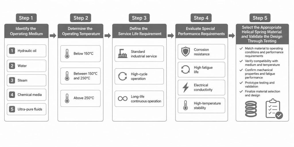
A Simple Helical Spring Material Selection Process
For most engineering projects, the material selection process can be simplified into the following steps:
Step 1 – Identify the Operating Medium Step 2 – Determine the Operating Temperature
- •Hydraulic oil •Below 150°C
- •Water •Between 150°C and 250°C
- •Steam •Above 250°C
- •Chemical media
- •Ultra-pure fluids
Step 3 – Define the Service Life Requirement Step 4 – Evaluate Special Performance Requirements
- •Standard industrial service • Corrosion resistance
- •High-cycle operation •High fatigue life
- •Long-life continuous operation •Electrical conductivity
•High-temperature stability
Step 5 – Select the Appropriate Helical Spring Material and Validate the Design Through Testing。
If you are developing a new Spring Energized Seal or optimizing an existing sealing system, our engineering team can recommend the most suitable Helical Spring material and spring configuration based on your operating pressure, temperature, media compatibility, installation space, and service life requirements.Talk to Our Engineers:Request Free Samples。
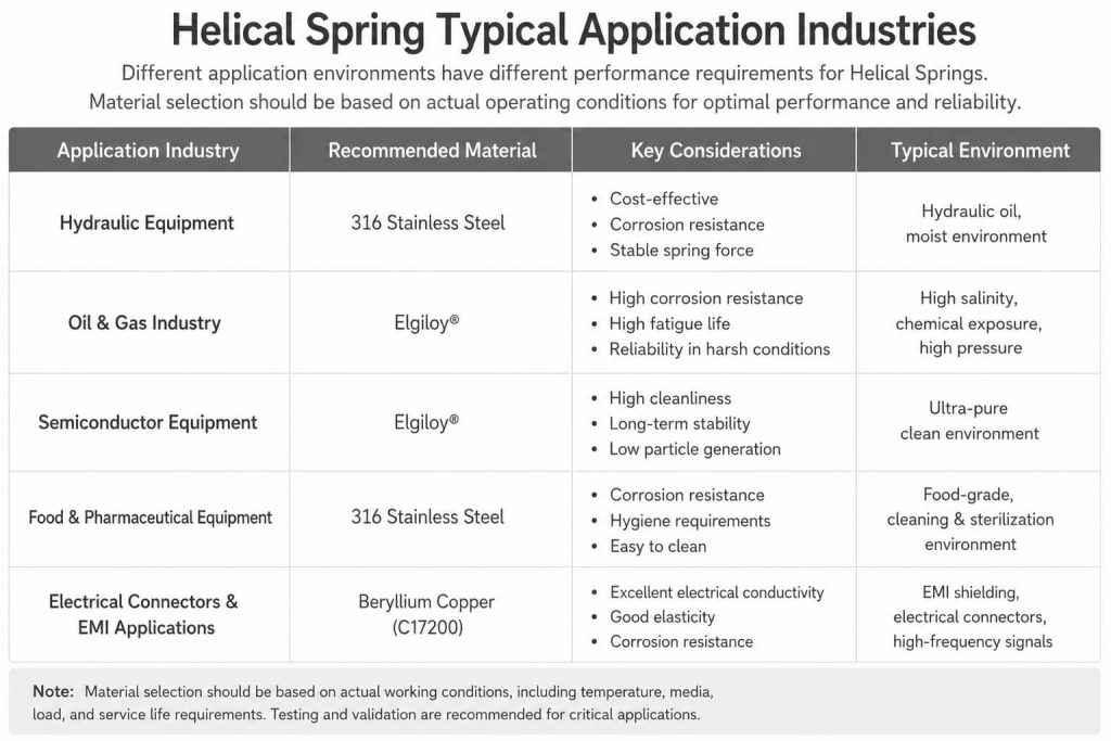
Typical Applications of Helical Spring Materials Across Industries
Different industries place different demands on sealing systems. As a result, selecting the right Helical Spring material should always be based on the specific operating conditions rather than a one-size-fits-all approach.
| Industry |
Recommended Material |
Primary Considerations |
| Industrial Hydraulics | 316 Stainless Steel | Balanced cost, corrosion resistance, and stable spring force |
| Oil & Gas | Elgiloy | Corrosive environments and long service life |
| Semiconductor Equipment | Elgiloy | High cleanliness and long-term spring force stability |
| Food & Pharmaceutical Equipment | 316 Stainless Steel | Corrosion resistance and hygienic requirements |
| Electrical Contacts & EMI Applications | Beryllium Copper (C17200) | Electrical conductivity and excellent elasticity |
Each material offers unique advantages. The goal is not to select the highest-grade material, but to choose the Helical Spring material that best matches the performance requirements of the application.
Common Mistakes When Selecting a Helical Spring Material
In many projects, the performance of a Helical Spring depends not only on the material itself, but also on how well it matches the application. The following issues are among the most common during the material selection process:
- •Focusing only on the maximum operating temperature. In many cases, continuous operating temperature, long-term loading, and resistance to stress relaxation are more important than the peak temperature rating.
- •Choosing premium materials unnecessarily. High-performance alloys such as Elgiloy® are not required for every application. For many industrial sealing systems, 316 Stainless Steel provides an excellent balance of performance, corrosion resistance, and cost.
- •Overlooking system compatibility. The performance of a Helical Spring also depends on factors such as seal material, groove design, compression ratio, and operating pressure. Optimizing the entire sealing system is essential for achieving long-term reliability.
Conclusion
Although a Helical Spring is a relatively small component within a Spring Energized Seal, it plays a critical role in maintaining sealing force, controlling friction, resisting corrosion, and ensuring long-term system reliability.
There is no single material that is ideal for every application. The best choice depends on the operating temperature, media compatibility, corrosion exposure, service life requirements, and overall project budget.
If you are developing a new Spring Energized Seal or looking to improve an existing sealing solution, our engineering team can help you select the most suitable Helical Spring material and spring configuration based on your specific application requirements.Talk to Our Engineers:We Speak Tech, Not Just Sales。