- Do you need help? Here Us:
- +86 13169905499
- sunny@handaspring.com
- Wechat:13169905499
 English
  中文 (中国)
 Chenzhou, Hunan, China(423000)

- 2026年4月7日
- handasprings
- Read: 342
Discover the most common canted coil spring groove design mistakes that lead to premature failure—incorrect depth and width, tolerance stack-up, sharp corners, and poor surface finish. Learn engineering best practices to optimize contact force and extend service life.
Introduction
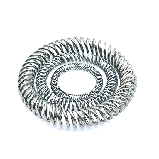
Canted coil springs (also known as slanted coil springs or oblique coil springs) are widely used in electrical contacts, EMI shielding gaskets, sealing systems, and precision mechanical assemblies due to their unique geometry and near-constant force output over a wide deflection range. Their angled coils roll rather than simply deflect when compressed, delivering consistent load distribution and high cycle life.
However, even the highest-quality spring will fail prematurely if the groove design is incorrect. Engineers often focus heavily on spring selection—material, plating, and force classification—but underestimate the critical importance of groove geometry. The groove is not merely a housing feature; it is the spring‘s operating environment. Small dimensional errors can push the spring outside its optimal working window, resulting in uneven load distribution, premature wear, loss of contact force, extrusion, or complete spring failure.
This guide explores the most common canted coil spring groove design mistakes, explains why they occur, and provides practical solutions to help engineers avoid costly redesigns and field failures.
Why Groove Design Matters
A properly engineered groove performs several vital functions for a canted coil spring:
-
Retaining the spring in position
-
Controlling compression and deflection
-
Maintaining proper contact force
-
Preventing extrusion under pressure
-
Allowing thermal expansion
Unlike conventional compression springs, canted coil springs rely on controlled interaction between the spring and its groove. The groove geometry directly affects spring deflection behavior, load consistency, retention and stability, wear and service life, and ease of installation. A poorly designed groove can negate all the advantages of a high-quality spring.
Because canted coil springs operate within precise deflection windows, even small dimensional errors can push the spring outside its working range. The following sections examine the most common mistakes in detail.
Mistake #1: Incorrect Groove Depth
The Problem
Groove depth is one of the most frequently miscalculated parameters. Engineers sometimes use generic seal groove dimensions borrowed from O-ring or compression spring designs, which are not suitable for canted coil springs. The result is a groove that is either too deep or too shallow.
-
Groove too deep → The spring is under-compressed. This reduces contact force, leading to micro-leakage in sealing applications or intermittent electrical contact.
-
Groove too shallow → The spring is over-compressed, forced beyond its elastic range. This causes plastic deformation, accelerated stress relaxation, and premature fatigue.
Research shows that over-compressed springs can lose 20–30% of their initial force within hours of installation, depending on material and operating temperature.
Impact on Performance
| Groove Depth Condition | Immediate Effect | Long-Term Failure |
|---|---|---|
| Too deep | Low compression | Loss of contact force |
| Too shallow | Over-compression | Plastic deformation, stress relaxation |
Best Practice
Design groove depth to achieve the manufacturer‘s recommended compression, typically 15–30% of free height, depending on the spring series.The groove depth must accommodate the spring’s free height, required working deflection, and assembly tolerances.Always consult the spring manufacturer‘s specifications—never guess or copy from other seal designs.
Mistake #2: Improper Groove Width
The Problem
One of the most common errors is specifying a groove width that is either too narrow or too wide. Either extreme leads to performance degradation.
-
Too narrow → Restricts the spring’s natural deflection, causing coil binding. Coils compress into each other unevenly, leading to high stress concentrations, installation difficulty, and early fatigue failure.
-
Too wide → Allows excessive lateral movement. The spring may wander, roll, or even dislodge from the groove during dynamic operation, resulting in uneven contact force and localized wear.
Consequences
| Groove Width Condition | Consequences |
|---|---|
| Too narrow | Spring binding, installation difficulty, coil distortion, uneven load distribution |
| Too wide | Spring wandering, misalignment, uneven wear, potential seal instability |
Best Practice
The groove width should allow controlled radial and axial movement without allowing the spring to twist or collapse. Always follow the spring manufacturer‘s recommended tolerances.Groove width is typically specified as 10–20% wider than the spring height to allow proper clearance while maintaining lateral control.
Mistake #3: Ignoring Tolerance Stack-Up
The Problem
Many designs look correct on paper when nominal dimensions are used, but fail in production due to tolerance accumulation. Engineers often design grooves based only on nominal values, overlooking the combined effect of individual tolerances on groove depth, spring height, and mating surfaces.
The Hidden Risk
Tolerance stack-up can significantly change actual compression, leading to dramatic performance variation across production units. Consider this example:
| Parameter | Nominal | Tolerance | Worst Case |
|---|---|---|---|
| Groove depth | 2.00 mm | ±0.05 | 2.05 mm |
| Spring height | 2.20 mm | ±0.05 | 2.15 mm |
| Actual compression | 0.20 mm | — | 0.10 mm |
In this scenario, compression is reduced by 50%, resulting in dramatic contact force loss.
Best Practice
-
Perform worst-case tolerance analysis—never rely on nominal values alone
-
Consider machining capability and process variation
-
Tight but realistic tolerances ensure consistent spring engagement and stable force output across the entire assembly
Mistake #4: Sharp Groove Corners and Poor Surface Finish
The Problem
Sharp internal corners and rough machining surfaces inside the groove are often overlooked but can severely damage a canted coil spring over time. Sharp edges act as cutting tools—as the spring compresses and expands, especially in dynamic or high-cycle applications, the coils rub against these sharp edges, causing abrasion, micro-cutting, and accelerated wear.
Consequences
Sharp corners and rough surfaces cause:
-
Coil abrasion and micro-cracks
-
Stress concentration at the groove base
-
Seal jacket damage (in spring-energized seal applications)
-
Spring snagging during installation
Best Practice
-
Add chamfers or radiused edges to the groove opening and internal corners
-
Specify a smooth surface finish on groove walls and mating surfaces
Recommended surface finish values:
This is especially critical for gold-plated or silver-plated canted coil springs used in electrical applications, where surface damage can dramatically increase contact resistance.
Mistake #5: Using the Wrong Groove Shape
The Problem
Not all grooves should be rectangular. Many engineers default to a simple rectangular groove without considering whether the application requires a different profile for retention, load distribution, or assembly.
Common groove shapes include:
-
Rectangular grooves – General-purpose, simple to machine
-
Dovetail grooves – Provides mechanical retention; prevents spring from falling out during assembly
-
V-shaped or tapered grooves – Alters load distribution and deflection characteristics
-
Stepped grooves – Accommodates different spring heights or multiple functions
Impact
Using the wrong groove shape leads to uneven load distribution, localized stress points, reduced mechanical and electrical efficiency, and potential spring dislodgement in high-vibration environments.
Best Practice
Select groove geometry based on:
-
Application type – Sealing, grounding, or electrical contact
-
Required deflection direction – Radial or axial
-
Retention needs – Whether the groove will be oriented upward or downward
-
Environmental conditions – Vibration, thermal cycling, debris exposure
Consulting with a canted coil spring manufacturer early in the design phase can prevent costly redesigns.
Mistake #6: Not Considering the Operating Environment
The Problem
Environmental factors are often overlooked in groove design. Engineers may specify groove dimensions based on room-temperature, dry conditions, but the actual operating environment—thermal expansion, corrosion, debris—can significantly alter groove geometry and spring performance.
Common Environmental Oversights
| Environmental Factor | Consequence |
|---|---|
| High temperature | Groove constriction, spring over-compression due to differential thermal expansion |
| Low temperature | Loss of contact force as housing contracts away from spring |
| Humidity / chemical exposure | Corrosion of spring or groove surfaces, increased contact resistance |
| Debris accumulation | Open grooves trap contaminants, causing abrasion and binding |
In aerospace, automotive, and semiconductor applications, thermal expansion effects are particularly critical. Groove design must account for differential expansion between the housing material and the spring material.
Best Practice
-
Account for the coefficient of thermal expansion of both housing and spring materials
-
Design groove dimensions and clearances based on actual operating conditions, not just nominal room-temperature values
-
Consider closed or semi-closed groove profiles in debris-prone environments
-
Specify corrosion-resistant materials or platings for humid or chemical environments
Mistake #7: Neglecting Groove Venting
The Problem
In sealing applications, trapped air or fluid pressure within the groove can prevent the spring from seating properly or cause extrusion under pressure. This is a subtle but critical mistake that often goes unnoticed until field failures occur.
Impact
Without proper venting:
-
Pressure buildup lifts the seal or spring off the mating surface
-
Extrusion occurs at high pressure
-
Seal leakage or spring dislodgement results
Best Practice
In high-pressure sealing applications, include vent grooves or pressure-relief ports to allow trapped media to escape. Consult the spring manufacturer for specific venting recommendations based on pressure rating and spring geometry.
Common Groove Design Mistakes Summary Table
| Mistake | Problem | Potential Impact | Best Practice |
|---|---|---|---|
| Incorrect depth | Too deep or too shallow | Loss of contact force or over-compression | Design for 15–30% compression of free height |
| Incorrect width | Too narrow or too wide | Coil binding or spring wandering | Follow manufacturer tolerances; typically 10–20% wider than spring height |
| Tolerance stack-up | Nominal-only design | Up to 50% force loss | Perform worst-case tolerance analysis |
| Sharp corners | No chamfers or radii | Coil abrasion, micro-cracks, stress concentration | Add chamfers or radiused edges (R ≥ 0.2 mm) |
| Poor surface finish | Rough machining marks | Increased friction, accelerated wear, debris | Static: Ra ≤ 1.6 μm; Dynamic: Ra ≤ 0.8 μm |
| Wrong groove shape | Rectangular when retention needed | Spring dislodgement, uneven load | Match shape to application (dovetail, V-shaped, etc.) |
| Ignored environment | No thermal or corrosion consideration | Over-compression at high temp, corrosion failure | Account for CTE; specify corrosion protection |
| No venting | Trapped pressure in sealing apps | Extrusion, seal lift-off | Add vent grooves or pressure-relief ports |
Best Practice Design Checklist
Before finalizing your canted coil spring groove design, verify the following:
-
Groove depth achieves manufacturer-recommended compression (15–30% of free height)
-
Groove width allows controlled movement without excessive clearance
-
Worst-case tolerance analysis has been performed—not just nominal values
-
Internal corners are chamfered or radiused
-
Surface finish meets recommended Ra values for static or dynamic application
-
Groove shape matches retention and load distribution requirements
-
Thermal expansion has been calculated for the full operating temperature range
-
Environmental protection (plating, corrosion resistance) is specified
-
Venting is provided for high-pressure sealing applications
-
Manufacturer specifications have been consulted and followed
Conclusion
Canted coil springs are exceptional components that deliver consistent force across wide deflection ranges, making them ideal for demanding applications in aerospace, medical devices, automotive systems, and EMI shielding. However, their performance depends critically on proper groove design. The groove is not simply a container—it is a functional partner that directly controls compression, stability, and load distribution.
The most common groove design mistakes—incorrect depth and width, tolerance stack-up, sharp corners, poor surface finish, wrong groove shape, ignored environmental factors, and lack of venting—can all lead to premature failure, inconsistent contact force, and costly field returns. By understanding these errors and applying the engineering best practices outlined in this guide, engineers can ensure their canted coil springs perform reliably throughout their intended service life.
When in doubt, consult the spring manufacturer early in the design phase. They can provide specific groove recommendations, force-deflection curves, and application engineering support to help you avoid costly mistakes and achieve optimal performance.
Need assistance with canted coil spring groove design for your application? Contact our engineering team for groove dimension recommendations, tolerance analysis support, and custom spring solutions.